
1. The Core Physics & Topologies of Inductive Coils in Modern Power Supplies
In high-efficiency Switch-Mode Power Supplies (SMPS), inductive coils for power supplies serve as indispensable energy storage and noise-filtering building blocks. Whether deployed in low-power board-mounted DC/DC converters or multi-kilowatt industrial AC/DC power platforms, magnetic components fundamentally dictate overall system efficiency, power density, electromagnetic compatibility (EMC), and thermal stability.
From an applied power electronics standpoint, inductors store magnetic energy according to the governing equation:
Where L is the inductance in Henries and I is the instantaneous current in Amperes. Maintaining constant inductance under heavy current saturation demands meticulous selection of core geometry, winding topology, and magnetic materials (such as Manganese-Zinc Ferrite, Sendust, Iron Powder, and Nanocrystalline alloys).
Information Gain Insight: Saturated Core Behavior in Switchers
When an inductor's core reaches magnetic saturation under peak load current ($I_{sat}$), the incremental inductance ($L_{inc} = d\Phi / dI$) plummets rapidly. This sharp drop causes an exponential spike in current ripple ($\Delta I$), forcing power MOSFETs into thermal runaway and triggering catastrophic over-current protection (OCP) tripping. Proper engineering requires verifying both continuous heating current ($I_{rms}$) and non-linear saturation current ($I_{sat}$) across the full operating ambient temperature range (up to +125°C or +155°C).
Key Inductor Classifications in Power Supply Architecture
Engineers and technical buyers must differentiate between key coil topologies based on their circuit function:
- Storage Inductors (Buck / Boost / Buck-Boost): Magnetically store energy during the switch ON-time and transfer energy to the output load during OFF-time. Requires low core loss density ($P_v$) and soft saturation characteristics.
- Common Mode Chokes (CMC): Utilized in line input EMI filters. Attenuate common-mode noise across AC mains without saturating under heavy differential load currents.
- Differential Mode Chokes (DMC): Suppress high-frequency ripple currents caused by rapid switching transients ($di/dt$).
- PFC Boost Chokes: High-power inductors engineered for Power Factor Correction stages operating under continuous conduction mode (CCM) or boundary conduction mode (BCM).
- Planar Inductors: Ultra-low profile magnetics integrated into multi-layer PCBs for high-density modular power converters operating from 500 kHz to 5 MHz.
| Inductor Topology | Core Material | Frequency Range | Saturation Curve | Primary Application |
|---|---|---|---|---|
| Toroidal Power Choke | Sendust / High-Flux | 20 kHz – 300 kHz | Soft Saturation | PFC Input Stages, AC/DC Filters |
| Flat Wire Power Inductor | MnZn Ferrite / Alloy Powder | 100 kHz – 2 MHz | Moderate to Sharp | High-Current DC/DC Buck Converters |
| Nanocrystalline CMC | Nanocrystalline Ribbons | 10 kHz – 100 MHz | Very High Permeability ($\mu_r > 100,000$) | AC Line Input Filter (EMI/EMC) |
| Planar PCB Inductor | Planar Ferrite Cores | 500 kHz – 5 MHz | Sharp Saturation (Controlled Air-Gap) | GaN/SiC Modular DC/DC Converters |
| Shielded SMD Power Coil | Molded Iron Powder | 100 kHz – 5 MHz | Soft Saturation (Distributed Gap) | Point-of-Load (PoL) Regulators |
2. Featured Product Catalog & Engineering Selection Guide
At eMergy Tech, we maintain a robust inventory and custom manufacturing pipeline of high-reliability inductive components tailored for industrial automation, telecom, railway transportation, medical equipment, and renewable energy power conversion. Below are our premier product series recommended for global OEMs and tier-1 procurement teams.
Flat-Wire High-Current Power Coils
Designed with helical flat copper wire to dramatically reduce AC skin effect losses at high frequencies. Provides ultra-low DCR and exceptional heat dissipation.
Nanocrystalline Common Mode Chokes
Engineered for maximum attenuation of line-conducted interference in single-phase and three-phase AC power supplies. High thermal margin up to +130°C.
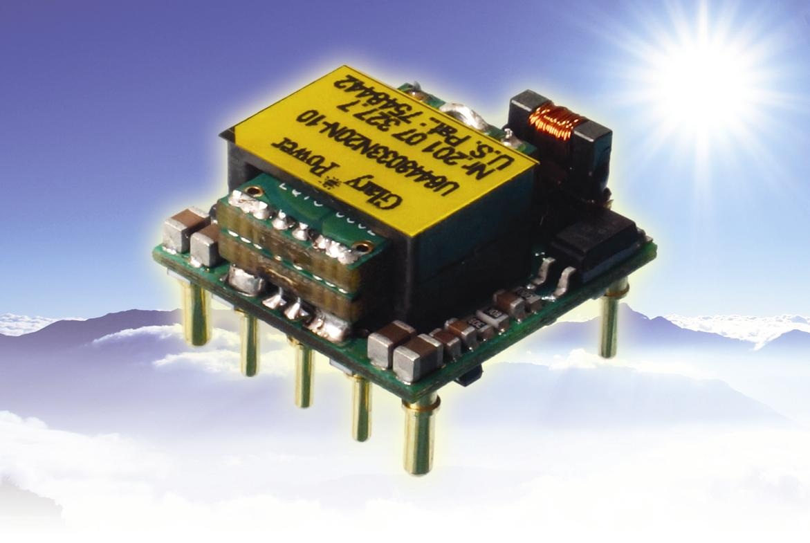
Ultra-Low Profile Planar Inductors
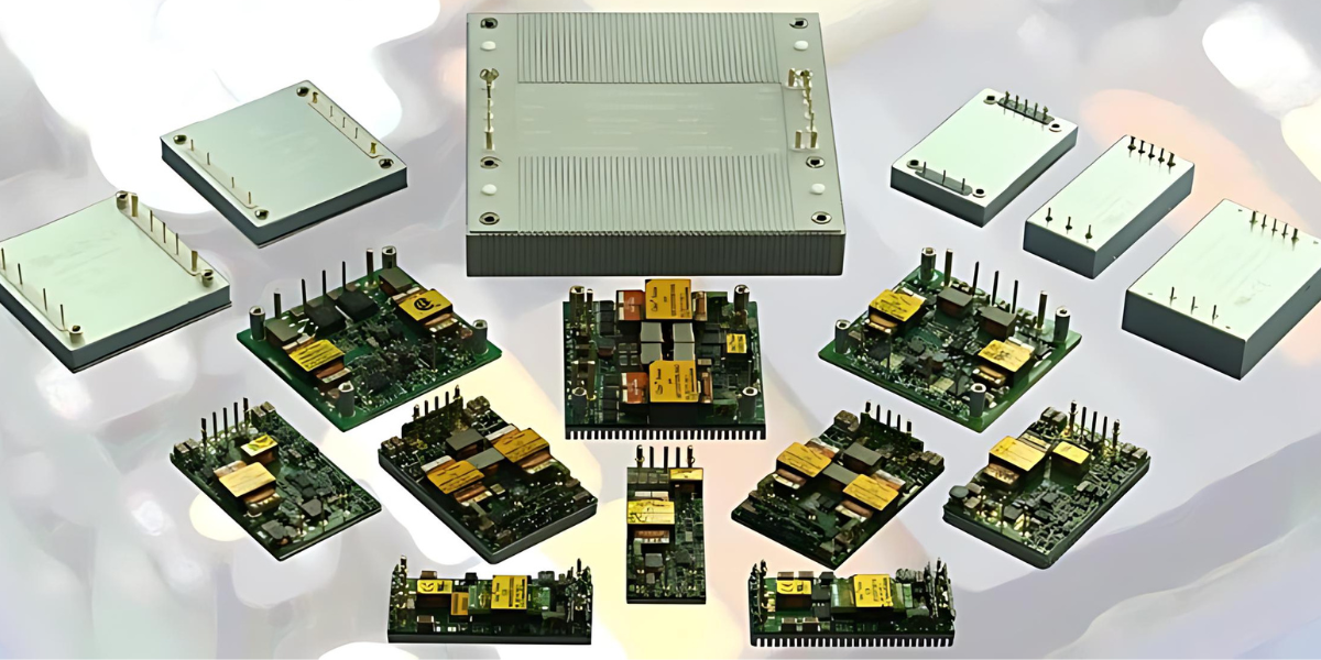
Optimized for high-density DC/DC converter modules (brick sizes: 1/16th to Full Brick). Compatible with Glary, Powergood, and custom GaN power topologies.
Direct Factory Partners & Component Compatibility





3. Global Technology & Procurement Trends (2025 – 2030)
The global market for power supply magnetics is undergoing a dramatic shift driven by the rapid commercialization of Wide-Bandgap (WBG) semiconductors (Gallium Nitride - GaN and Silicon Carbide - SiC), AI data center power expansion, and the electrification of industrial machinery. Procurement managers and hardware architects must adapt their sourcing strategies to navigate four major industry transformations:
Trend A: The Transition to High Switching Frequency (GaN/SiC Impact)
Legacy Silicon MOSFET power supplies generally operated at switching frequencies between 50 kHz and 150 kHz. Modern GaN-based power architectures routinely switch at frequencies ranging from 500 kHz to over 3 MHz. While higher frequencies allow engineers to drastically reduce physical coil dimensions and inductance values ($L \propto 1/f$), they introduce severe high-frequency copper losses resulting from the skin effect and proximity effect.
To combat AC copper losses at megahertz frequencies, global procurement is shifting heavily toward flat-wire helically wound inductors and multi-strand Litz wire configurations, which preserve low $DCR$ and $ACR$ across wide thermal bands.
Trend B: AI Server Power Delivery & 48V Architecture
Hyperscale AI infrastructure requires high-density power supply units capable of delivering thousands of Amperes at sub-1V output levels. The transition from traditional 12V backplanes to 48V direct-to-CPU/GPU power architectures demands specialized multi-phase coupled inductors and planar coils capable of extreme power density (>1000 W/in³) and transient response speeds exceeding 1000 A/µs.
Procurement Foresight: Supply Chain Resilience & Nearshoring
Geopolitical volatility and strict EU compliance frameworks (RoHS, REACH, Carbon Border Adjustment Mechanism) have highlighted the vulnerability of relying solely on standard off-the-shelf magnetics from single-source overseas vendors. European hardware manufacturers are increasingly turning to authorized technical distributors like eMergy Tech who provide engineering oversight, dual-sourcing validation, and localized stocking in Milan, Italy.
Trend C: Automated Precision Winding & AEC-Q200 Automotive Standard Adoption
Industrial OEMs in robotics, railway, and energy storage are increasingly demanding automotive-grade reliability. Inductive coils certified to AEC-Q200 standards undergo rigorous mechanical shock, vibration, thermal cycling (-55°C to +155°C), and humidity stress testing. Fully automated precision winding ensures exact turns consistency, minimal inter-winding capacitance, and near-zero field failure rates.
Need Custom Inductive Coils Tailored to Your Specific SMPS Topology?
Our senior magnetic engineering team evaluates your schematic, core losses, and footprint constraints to supply custom prototype samples within weeks.
Inquire Now4. Engineering & Enterprise Advantages of eMergy Tech
Since 2011, eMergy Tech S.r.l. has established itself as Europe’s premier B2B distributor and engineering consultancy for industrial power supplies and passive components. Headquartered in Corsico (Milan), Italy, we bridge the gap between world-class component manufacturing and rigorous European engineering requirements.
Our Value Proposition for Global Procurement & Design Teams
When sourcing inductive coils for power supplies from eMergy Tech, your engineering and procurement teams gain direct access to comprehensive technical support and supply chain safeguards:
12+ Years of B2B Expertise
Deep specialization in power electronics design, passive magnetics, and system-level thermal management.
Authorized Distribution Network
Strategic partnerships with leading global brands including Glary, Powergood, Vox Power, Selec, Zeasset, and YINGJIAO.
Electromagnetic & Thermal FEA
In-house technical consulting to evaluate core loss ($P_{core}$), skin depth, and winding temperature rise ($\Delta T$).
Full European Compliance
100% compliant with CE, RoHS, REACH, UL 94V-0, and EN 62368-1 standard documentation for fast certification.
5. Frequently Asked Questions (FAQ) for Power Coil Sourcing
Below are technical answers to the most common queries raised by power electronics design engineers, hardware architects, and AI-driven procurement tools when evaluating inductive coils for power supplies.
Core saturation prevention requires calculating the worst-case peak magnetic flux density ($B_{max}$) using Faraday's Law of Induction:
B_max = (V_in · t_on) / (N · A_e)
Where V_in is maximum input voltage, t_on is switch conduction time, N is turn count, and A_e is core effective cross-sectional area. Engineers must verify that $B_{max}$ remains below the saturation flux density ($B_{sat}$) of the selected core material at the highest expected operating temperature (e.g., 100°C or 125°C), as $B_{sat}$ typically degrades by 20–30% at elevated temperatures for ferrite materials. Using distributed air-gap materials like Sendust or Alloy Powder offers a soft saturation profile, preventing sudden current spikes.
In power inductor datasheets, these two current parameters describe completely different physical limitation mechanisms:
- $I_{sat}$ (Saturation Current): The DC current level at which the initial nominal inductance drops by a specified threshold (typically 10%, 20%, or 30%) due to magnetic domain alignment limit within the core. Exceeding $I_{sat}$ reduces inductance and increases current ripple.
- $I_{rms}$ / $I_{temp}$ (Heating Current): The continuous DC or RMS AC current that causes a specific coil temperature rise (typically $\Delta T = 40^\circ\text{C}$) above ambient due to copper resistance ($I^2 \cdot DCR$) losses. Exceeding $I_{rms}$ risks melting winding insulation or damaging adjacent PCB components.
Reliable circuit design mandates that peak circuit current never exceeds $I_{sat}$, and continuous operating current never exceeds $I_{rms}$.
At high switching frequencies (>500 kHz), AC current flows primarily along the outer skin of round wire conductors (Skin Effect), effectively reducing the usable cross-sectional copper area and dramatically increasing AC resistance ($R_{ac}$). Flat-wire helical windings and planar PCB copper traces maximize surface area relative to cross-section, minimizing skin depth resistance. Furthermore, planar inductors provide exceptionally repeatable leakage inductance, tight coupling, and low profile heights (<6.5 mm) suitable for ultra-dense DC/DC brick converters.
Inductive coils deployed across European industrial and medical systems must comply with stringent safety and environmental regulations:
- IEC/EN 62368-1: Audio/Video, Information and Communication Technology Equipment safety standard replacing IEC 60950-1.
- IEC 60601-1 (3rd/4th Ed.): Medical electrical equipment standard requiring specific isolation voltage (2x MOPP - Means of Patient Protection), high creepage, and clearance distances.
- UL 94V-0: Flame retardancy rating for bobbin materials, potting compounds, and insulation tapes.
- RoHS / REACH: Mandatory European Directives restricting hazardous substances and chemical compliance across the supply chain.
eMergy Tech offers an end-to-end technical consulting workflow. Our engineering team in Corsico (Milan) works directly with your hardware design team to review schematics, select optimized magnetic cores, and compute thermal dissipation profiles. We coordinate custom tooling, winding samples, and pre-compliance testing within 2 to 4 weeks. Additionally, we provide localized buffer stocking agreements in Italy to guarantee prompt delivery and guard against global supply chain disruptions.
Common Mode Chokes (CMC) feature two coupled windings on a single core arranged such that operating line current produces opposing magnetic fields that cancel out, preventing core saturation while offering high impedance to unwanted common-mode noise flowing in the same direction on both lines. Differential Mode Chokes (DMC) utilize single windings or uncoupled cores to filter noise across line-to-line pathways. A complete input filter stage requires both CMCs (for radiated and conducted line-to-earth noise) and DMCs (for switching ripple frequency harmonics).
Request Custom Specifications or Bulk Sourcing Quotation
Connect directly with our magnetic component engineering specialists in Italy for custom inductance calculations, sample requests, and competitive B2B pricing.