Choosing Inductive Coils for Power Supplies requires more than matching inductance values on a datasheet. The coil must handle ripple current, switching frequency, heat, and mechanical limits. A component rated at 10 µH may perform poorly when its core approaches saturation. This can increase losses, noise, and voltage instability. Small details matter.
In practical power supply development, engineers compare DC resistance, rated current, saturation current, core material, and temperature rise. They also inspect winding construction and shielding requirements. A compact shielded coil may reduce electromagnetic interference near sensitive control circuits. A larger air-gapped design may tolerate higher energy storage. The correct choice depends on the converter topology, input conditions, output load, and available board space.
Testing remains essential. Measure the coil under realistic switching conditions, not only with a bench meter. Check its temperature after continuous operation. Listen for audible vibration. Review the supplier’s test methods and confirm whether ratings apply at the intended temperature. Experience helps, but it can also create assumptions. A familiar part may fail in a new layout. No selection method is flawless.
This guide explains how to evaluate Inductive Coils for Power Supplies with practical engineering judgment. It connects electrical specifications with real operating behavior. Readers will learn how to compare candidates, identify hidden trade-offs, and avoid common selection mistakes. Reliable sourcing also matters. Use traceable manufacturers, current documentation, and controlled verification before production. A careful choice improves efficiency, stability, service life, and overall power supply reliability.
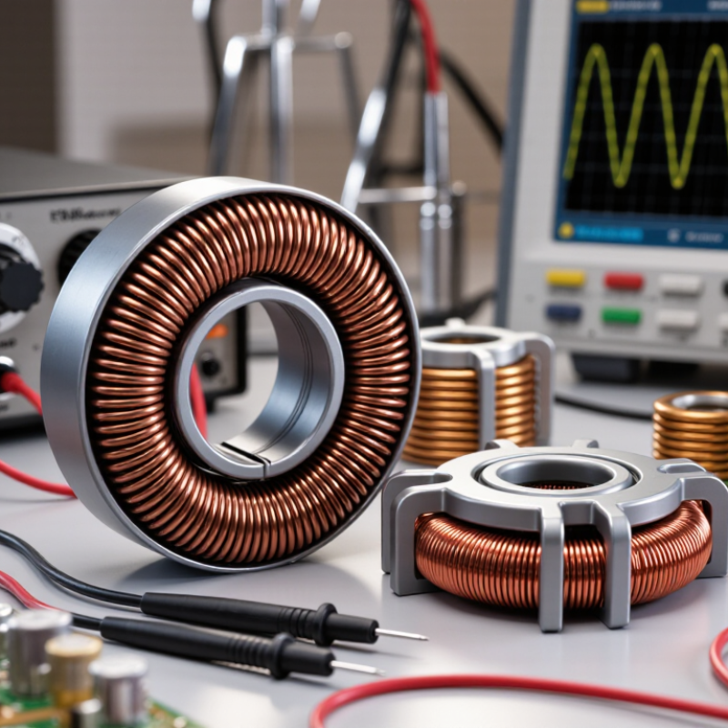
Understanding Inductive Coils and Their Role in Power Supplies
Inductive coils, or power inductors, temporarily store energy in a magnetic field. In a switching power supply, they smooth current between the switch and capacitor. This reduces ripple and protects sensitive loads. The coil also limits sudden current changes. That role becomes critical as switching frequencies rise.
The International Energy Agency’s Electricity 2024 report projects global electricity demand will grow by about 3.4% annually through 2026. It also expects renewables to meet more than 90% of added demand. These trends increase pressure for efficient, compact power conversion. Selecting an inductor requires more than checking inductance. Review saturation current, RMS current, DC resistance, core loss, and temperature rise. A larger coil is not automatically safer.
During bench evaluation, measure ripple at the real load, not only under a light test. A 10 µH part may appear suitable, yet its inductance can fall sharply near saturation. The U.S. Department of Energy’s efficiency guidance for external power supplies also emphasizes performance across load conditions, not just peak efficiency. That principle applies here. Check the datasheet’s test frequency and temperature. They may not match your circuit. Keep traces short, leave thermal clearance, and verify noise with an oscilloscope. Small errors matter.
Identifying Key Electrical and Mechanical Coil Specifications
How to Choose Inductive Coils for Power Supplies?
Inductive coils influence ripple current, efficiency, heat, and converter stability. Start with inductance, saturation current, rated RMS current, and DC resistance. The saturation rating shows where inductance drops sharply. It is not a safe operating target. Select a coil with practical current margin, often 20–30% above the expected peak. The IEEE 2023 Global Survey on Power Electronics highlights efficiency and thermal control as continuing design priorities. That makes low DCR especially important in compact power supplies. However, lower resistance often means a larger component. Real designs require compromise.
Mechanical specifications deserve equal attention. Check the body length, height, terminal layout, mounting strength, and operating temperature range. Shielded construction can reduce magnetic interference near sensors or communication circuits. Verify the coil’s self-resonant frequency when switching edges are fast. A component may meet its inductance value but still behave poorly at high frequency. The IEA Electricity 2024 report projects strong global electricity-demand growth through 2026, increasing pressure for efficient power-conversion hardware. The report does not specify coils, but its direction is relevant. Datasheet tolerances can also be optimistic. Measure samples when reliability matters.
Tips: Calculate peak current from the actual waveform, not only the average value. Compare DCR at the working temperature. Leave copper clearance around the magnetic path. Test audible noise under light load. A perfect coil does not exist. Recheck ripple, temperature rise, and EMI on the assembled board. Use IEC 62024-2 guidance where applicable, then document your measurement conditions for repeatable decisions.
Matching Inductance and Current Ratings to Power Supply Needs
Choosing an inductive coil starts with the converter’s real operating conditions. Calculate inductance from switching frequency, input voltage, output voltage, and allowable ripple current. For a buck converter, L = Vout(1 − D) ÷ (ΔI × fs). A ripple target near 20–40% of maximum load current often balances response and size. It is only a starting point.
Current ratings need closer attention. Saturation current limits the peak ripple current, while RMS current determines heating through winding resistance. Do not compare these ratings as if they mean the same thing. On a bench, a coil can pass its rated current yet exceed safe temperatures inside a sealed enclosure. Leave practical margin for startup, overload, and temperature rise. A 20% margin may be inadequate when airflow is poor. I have seen calculations fail there.
Tips: Check both saturation and temperature ratings at the highest expected temperature. Measure ripple with the final layout, not only in simulation. Keep the coil away from sensitive signal traces. The IEA’s Electricity 2024 report projects data-centre electricity demand could exceed 1,000 TWh by 2026, increasing pressure for efficient power conversion. Lower DCR reduces conduction loss, but a smaller coil may raise ripple and EMI. The compromise is real. Recheck it.
How to Choose Inductive Coils for Power Supplies? - Matching Inductance and Current Ratings to Power Supply Needs
| Power Supply Use |
Input Voltage |
Output Requirement |
Switching Frequency |
Target Ripple Current |
Calculated Minimum Inductance |
Recommended Nominal Inductance |
Required RMS Current |
Recommended Saturation Current |
Maximum DCR |
Preferred Construction |
| Logic rail buck converter |
18–30 V DC |
5 V / 2 A |
500 kHz |
0.60 A p-p |
13.2 µH |
15 µH |
≥ 2.01 A |
≥ 2.60 A |
≤ 70 mΩ |
Shielded power inductor |
| Embedded controller supply |
9–16 V DC |
3.3 V / 5 A |
600 kHz |
1.50 A p-p |
2.6 µH |
3.3 µH |
≥ 5.02 A |
≥ 5.90 A |
≤ 18 mΩ |
Low-profile shielded type |
| Industrial 12 V rail |
18–30 V DC |
12 V / 3 A |
300 kHz |
0.90 A p-p |
22.2 µH |
27 µH |
≥ 3.01 A |
≥ 3.70 A |
≤ 45 mΩ |
Shielded ferrite-core type |
| High-current communications rail |
36–60 V DC |
12 V / 8 A |
400 kHz |
2.40 A p-p |
3.75 µH |
4.7 µH |
≥ 8.03 A |
≥ 9.80 A |
≤ 10 mΩ |
High-current shielded type |
| LED constant-current converter |
12–24 V DC |
36 V / 1 A |
250 kHz |
0.30 A p-p |
20.0 µH |
22 µH |
≥ 1.01 A |
≥ 1.30 A |
≤ 120 mΩ |
Low-noise shielded type |
| Battery-powered portable device |
3.0–4.2 V DC |
5 V / 1.5 A |
1.2 MHz |
0.45 A p-p |
2.9 µH |
3.3 µH |
≥ 1.50 A |
≥ 1.80 A |
≤ 90 mΩ |
Compact molded type |
| Power-over-data input filter |
24–57 V DC |
Input filtering / 0.6 A |
150 kHz noise band |
Not applicable |
Design-specific |
47 µH |
≥ 0.60 A |
≥ 1.00 A |
≤ 250 mΩ |
EMI-rated shielded type |
|
Selection note: The calculated minimum inductance values are based on typical buck-converter operating points and an estimated inductor ripple current. Select a nominal value from the next standard range, then verify peak current, saturation behavior, temperature rise, copper loss, core loss, transient response, and the converter manufacturer's recommended operating range. Required saturation current should exceed the maximum inductor peak current with design margin.
|
Evaluating Core Materials, Winding Designs, and Energy Losses
Choosing an inductive coil begins with its operating frequency, ripple current, and temperature rise. Ferrite cores suit high-frequency switching because their electrical resistivity limits eddy-current loss. Powdered iron offers distributed air gaps and handles DC bias well. Nanocrystalline materials can provide high permeability, but cost and saturation behavior need careful review.
Winding design changes the result significantly. Thick wire lowers DC resistance, yet skin and proximity effects increase at higher frequencies. Litz wire can reduce AC resistance, while foil windings improve current distribution in compact converters. Interleaved layers may reduce leakage inductance, but they can increase interwinding capacitance. Measure both.
The U.S. Department of Energy’s Distribution Transformer Technical Support Document estimated annual transformer losses near 61 billion kWh in the United States. That figure shows why small efficiency gains deserve attention. Core loss should be checked across the actual flux waveform, not only at rated frequency. Copper loss follows I²R, but thermal conditions alter resistance. I have seen first-pass simulations look convincing, then fail during hot testing. Imperfect models happen. Use impedance measurements, temperature mapping, and worst-case saturation tests before approval. EIA reports that transmission and distribution losses commonly remain near 5% of generated electricity, reinforcing the value of disciplined magnetic design.
How to Choose Inductive Coils for Power Supplies?
Representative core-loss density by material and switching frequency
Values are representative engineering estimates at approximately 50 mT peak flux density and 100°C. Core loss rises sharply with frequency, especially in powdered materials. MnZn ferrite is commonly preferred for high-frequency power supplies because of its relatively low loss, while nanocrystalline and powdered cores can provide higher energy density or inductance but may require careful thermal and frequency evaluation. Winding designs such as litz wire, foil, or optimized single-layer windings can further reduce AC copper loss caused by skin and proximity effects.
Selecting, Testing, and Installing the Right Inductive Coil
How to Choose Inductive Coils for Power Supplies?
Selecting, Testing, and Installing the Right Inductive Coil
Selecting an inductive coil starts with the power supply’s voltage, current, switching frequency, and ripple target. Check the required inductance under real operating current, not only the value printed on a datasheet. A coil may lose inductance near saturation. That mistake can increase ripple, heating, and switch stress. Review saturation current, RMS current, direct-current resistance, and temperature rise. I once selected a coil by size alone. It fit neatly, but became hot during a 30-minute load test. Small was not better.
Tips: Leave current margin, often 20–30 percent above normal demand. Compare data measured at similar frequencies. Use a shielded construction when sensitive circuits sit nearby. Keep the power loop short and wide. Avoid placing the coil beside magnetic sensors or communication traces.
Testing should happen before final installation. Measure inductance with an LCR meter at a relevant frequency. Then apply the expected current and inspect ripple with an oscilloscope. Watch the coil’s surface temperature after steady operation. A thermal camera helps, but a simple temperature probe can reveal problems too. Check for audible noise, especially during light-load operation. Installation also matters. Solder firmly, control lead length, and follow the recommended pad layout. Leave airflow around the component. Recheck the design after enclosure assembly, because nearby metal can alter magnetic behavior. Some choices still require compromise. The quietest coil may not be the smallest or cheapest.
Conclusion
Choosing the right Inductive Coils for Power Supplies requires a clear understanding of how coils store and release energy, reduce current ripple, filter noise, and support stable power conversion. Start by reviewing essential electrical specifications, including inductance, rated current, saturation current, resistance, tolerance, operating frequency, and temperature range. Mechanical factors such as size, mounting method, clearance, and thermal management are equally important for reliable integration.
The coil should match the power supply’s load profile and switching conditions without excessive heating or magnetic saturation. Core material and shape affect energy storage, efficiency, electromagnetic interference, and loss performance, while winding design influences resistance, parasitic effects, and heat dissipation. After selecting a suitable component, verify its characteristics through electrical and thermal testing under realistic operating conditions. Careful installation, secure connections, appropriate spacing, and effective cooling can further improve reliability and service life. A balanced evaluation of performance, efficiency, physical constraints, and testing results helps ensure the selected coil meets the power supply’s practical requirements.